At the current level of program development Induction Pulse Theory is not applied. The reasons for this have been indicated earlier (see History - Resonant Functions). Users should however be fully aware that inlet tract loss is accounted for in calculations. Changing the choke diameter or the tract length will change the shape of the power curve.
A facility is provided to adjust the Induction Tract pipe loss. The program applies the following formulae to determine this.
p = L x V x V / 25000 x d = loss of pressure
ounces per square inch
L = length of pipe in feet.
V = velocity of air in ft per second.
d = inside diameter of pipe in inches.
Due to the potential range of pipe size and shape, the constant 25000 may need to be changed to suit engine capacity and RPM range. This constant is in fact the Reynolds number, which changes due to Velocity, Gas density and Temperature. The equation does not include facility for other than parallel pipes. Users should observe the step by step escalation of loss indicated in evaluation table of Induction (Yellow C button to observe) over a range of RPM and set accordingly.
The higher the Velocity the higher the loss, highest velocity may occur at modest RPM. It will be necessary to vary the Tract length and choke diameter to determine the affect on BHP and Scavenge Efficiency over the desired RPM range.
An option is provided to calculate the Reynolds numbers automatically during induction. The RN changing during the acceleration and deceleration of the induction flow. This Option may cause problems due to high gas velocity at low RPM with Choke/Induction pipe diameters less than one inch (model engine size). However it is more likely this is caused by unsuitable Combustion Burn Speed and Advance settings. When checking small/intermediate throttle openings users may find it necessary to apply the fixed RN condition, whilst minimum RPM and Combustion settings are established.
The program applies the following formulae to calculate the Reynolds number.
RN = ( Velocity x Choke Diameter x Gas Density ) / ( Kinematic Viscosity x Temperature )
Velocity in ft per sec
Choke Diameter in ft
Gas Density = 0.076 lb per cubic ft
Kinematic Viscosity FPS units = 0.131 x 0.001 (at zero
degrees C)
Temperature deg C = 1 deg applied,
see Help Induction Temperatures Table 3
This is near zero degrees during Induction.
During Induction the incremental expansion which takes place is a consequence of Gas Friction and Fuel Vaporisation. The incoming fuel mixture cools the crankcase and its contents causing a drop in pressure. Atmospheric Pressure forces the mixture into the crankcase as the piston moves increasing the crankcase volume. The Induction port is kept open beyond TDC to allow time for Gas Flow Inertia to raise the Crankcase Pump to Atmospheric Pressure.
The system is RPM sensitive, given sufficient time there would be no pressure drop. This is why it is necessary to close the throttle or apply a choke to start the engine. If the Intake velocity is too low no fuel will exit the jet.
The Crankcase Pump PV diagram is shaped like a boot, the area contained within this represents the work done during Induction. The Pump (Crankcase) pressure indicated is the consequence of piston movement and change in content. It should be observed how little the drop in pressure is during induction with a Rotary Valve system, with an open throttle this rarely exceeds 2 psia. Pressure at the jet may be somewhat different because this is subject to local flow. A consequence of this is that if the Gas Inlet Tract Speed is low pressure fuel feed may be required.
There are two distinct systems for fuel delivery applied to small model engines. The distinction between them is the difference in supply pressure, this is relevant to the vaporisation process. Despite the slang term Suction-Feed this is in fact a pressure system providing less than Atmospheric Pressure. Systems which provide greater than Atmospheric Pressure are known as Pressure Feed.
It is possible to produce a pressure system with a delivery pressure no greater than 14.7 psia. Such a system would present a problem to the rule makers. The Fuel exits the jet due to the Pressure difference between the Induction Tract and Fuel Tank.
The Induction Tract can be varied in shape to enhance the vaporisation process. Whilst it might be assumed that a Venturi type arrangement was required this is not confirmed by practical tests. A parallel Intake Tube with peripheral jet orifices operates in a similar manner to a sent spray, and can be equally effective.
A Throttle is fitted to an engine to restrict engine RPM, Throttle opening or Choke size is not as critical as some would imagine. It only needs to be large enough to enable the correct Fuel to Air Ratio at the desired RPM. In model circumstances the Fuel mixture Ratio is set manually. Hence the choke size should be optimised to suit the desired propeller, this should ensure that the mixture can be set Rich or Lean. If the engine is ultra critical on a lean setting then either the choke size is too large or the Induction Pump Efficiency is inadequate. Recent tests on my Dynamic Dominator 21D showed that when fitted with a 4 mm Spray Bar and Choke sizes from 6.5 to 8 mm diameter there was no significant change in sensitivity. Available RPM did increase as larger chokes were fitted proving that a Throttle is a Brake restricting performance. Hence choke size could be incorporated into rules should it be desired to restrict engine performance.
There appears to be very little to gain in performance if the Mechanical Efficiency of the engine is inadequate to support a larger choke size. All porting must be appropriate to this.
All flow calculations are made at the specified choke diameter (full throttle). If the Induction port area is greater than that of the choke during the inlet process, then the choke area is applied to calculate the flow. During the open and close phase of the ports the lesser area is applied, very high velocities can occur in these circumstances. Flow velocity in ft per sec can be compared between tract and port enabling comparison to the speed of sound at different RPM.
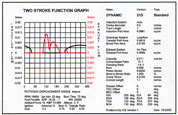
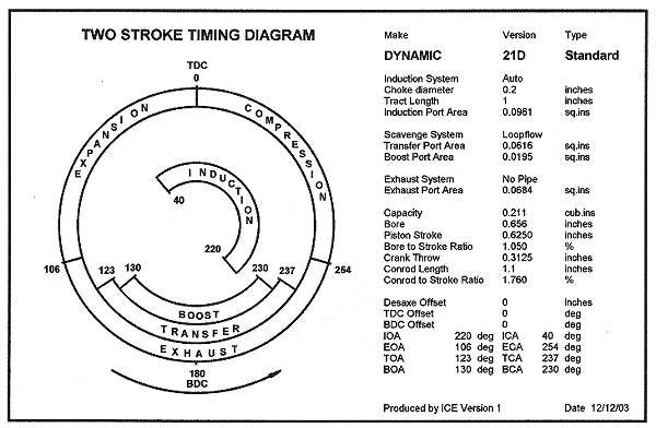
The Induction flow graph illustrated here demonstrates the function of an automatic inlet system, the timing of the cylinder ports is the same as the D21D with a crankshaft rotary induction port. Whilst the timing diagram illustrates a fixed timing for induction this changes according to pump pressure. The data is required by the program to enable calculation, this is specified in the engine database. If the user needs to know the actual open and close of the valve, observe the flow data produced at one-degree intervals at the specific RPM. The timing is most unlikely to remain constant.
The problem with this type of system is to design an arrangement with a high enough flow rate.