ICE is structured in a manner which links all engine Thermodynamic and Mechanical functions so that the outcome of calculation is interactive, this ensures that the output has a relationship to an engines cycle of operation. Whilst sophisticated routines for specific functions might be desirable they can be misleading if the input data does not reflect the correct start conditions. Some Empirically based equations have proved unsatisfactory when subjected to computer testing. Hence only basic routines which do not create mathematical errors can be applied. What this shows is that the available knowledge is limited, and subject to further investigation. Prediction of a specific function whilst useful is of little value if it is not linked to other concurrent conditions during engine operation. Whilst ICE applies relatively simple routines Users should appreciate the importance of the programming and prediction method.
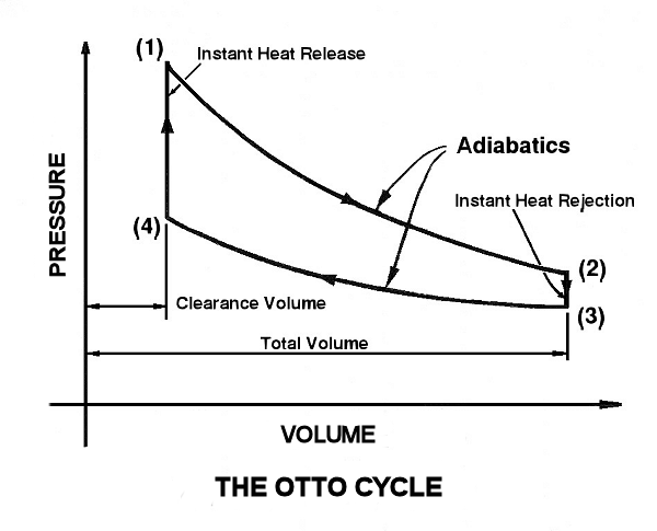
Two-Strokes Engines operate on the 'OTTO CYCLE' this is also known as the Ideal Cycle. This cycle is based on Instant Heat Release and Rejection, in actual engines the diagram shape is changed because Instant Release and Rejection is not obtained.
The program applies the Otto Cycle to determine the Engine Performance. At each RPM test case three crankshaft rotations are made for calculation purposes. All functional data output is calculated at one-degree intervals, this is displayed in table form. This is required so that a degree of accuracy is achieved, just as with an actual engine starting up, the pump and cylinder performance stabilises. The two-stroke engine is a resonant system hence performance (temperature, pressure and gas flow) depends on prior events. Optimum performance is therefore obtained when all functions resonate at the desired RPM.
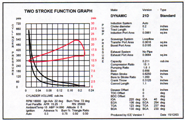
The above diagram shows an actual, calculated, curve (the black line is Cylinder Pressure, and the red crankcase). Note that the curve shape is modified by lack of instant heat release.
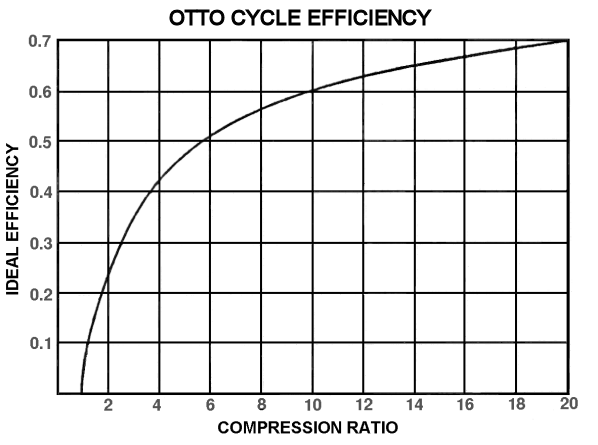
COMPRESSION RATIO
It is important that the most suitable compression ratio is applied reference the curve below.
PERFORMANCE
The earlier PV diagram is produced from data indicated in the Engine Function Tables - Thermodynamics.
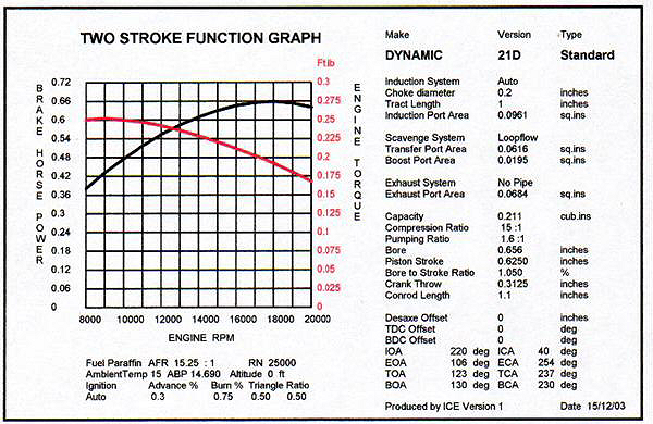
A second table display is featured to display output over a range of test RPM. This is used to establish Performance data such as IHP, BHP, Torque, FHP etc. Whilst tables of numerical data are useful for detail analysis, presentation in the form of graphs can provide a pictorial illustration of the function being investigated. ICE includes facilities for presentation in this form, 4 options for the X-axis are provided. These are -
1. Displacement Angle in degree's of Rotation
2. Piston Travel (Engine Stroke)
3. Cylinder Volume
4. Engine RPM
The Y-axis options are too many to list here, see ICE USER HELP for an indication of the current options. Two Y-axis scales are provided, this permits both BHP and Torque to be presented on the graph. It does not provide facilities to compare functions of an identical nature, separate graphs must be calculated and plotted for this purpose.