To produce a Timing Diagram click the ![]() button. The only prerequisite is to have an engine selected.
button. The only prerequisite is to have an engine selected.
The diagram follows the usual ICE convention of having the plot on the left, with engine details on the right. A timing diagram is a representation of the 360 degree cycle with zero degrees (TDC) at the top and 180 degrees (BDC) at the bottom. An arrow at BDC indicating the direction of rotation. The outer ring shows which segments of the cycle are used for compression, exhaust, and expansion. The centre of the diagram displays the induction period, and boost and transfer (if applicable) are displayed. The values displayed are calculated based on dimensions from the engine database. The numbers shown are in degrees and indicate the point at which any part of the the port(s) first become exposed and become totally closed.
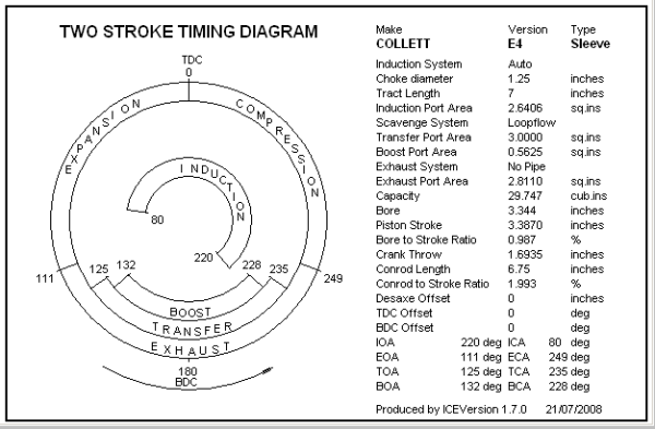
The above diagram is for the Collett E4 engine.
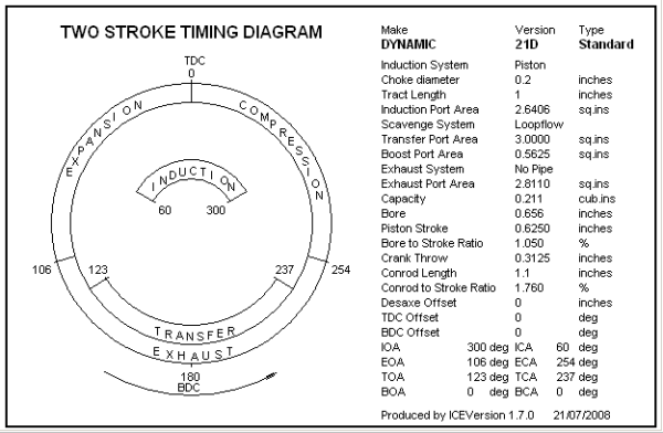
The above diagram is for the Dynamic 21D engine. The 21D has no Boost ports.
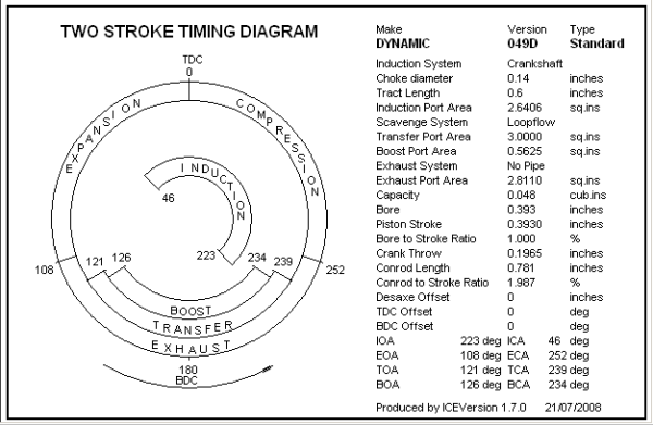
The above diagram is for the Dynamic 049D engine.