The technology for a Two-Stroke engine is substantially different to a Four-Stroke. There are many instances where a particular design feature is claimed to enhance performance. Do not assume that published statements are correct, there are frequently vested interests at stake. This is further complicated by the different scavenge systems employed. A uniflow scavenge Two-Stroke is ideally suited to Supercharging, it may not be beneficial with natural aspiration. Design features, which suit a supercharged engine, can be detrimental to a naturally aspirated design.
Combustion chamber squish is said to be beneficial to combustion, this may not be correct for all scavenge layouts. In the case of four-strokes improved scavenging could equally be responsible for the increase in performance achieved (the burnt gas being displaced into the combustion chamber when inlet and exhaust ports are open). In the case of loopflow Two-Strokes without direct fuel injection it would appear that the combustion chamber shape should not have any pockets, which might disrupt the scavenge flow. The important features are compression ratio and plug location. The distance of the plug electrode from the piston crown can be critical if melt down of the piston or burnt out plugs are to be avoided. The combustion temperature places a limit on the potential cylinder pressure. For engines with aluminium alloy pistons the maximum practical temperature is 2400 degrees C (2673 degrees C Absolute). In order to keep within this limit it may be necessary to reduce the compression ratio (ICE produces an audible warning when running the Performance function if this occurs).
The ignition advance and combustion period can be set manually, whilst this is ideal for investigation, the accuracy is limited when generating a performance curve. This is most pronounced in model engine size, the problem is associated with flame travel rates. The smaller the cylinder capacity the shorter the combustion period, hence small cylinders permit extended RPM. As RPM is increased the number of degrees rotation required for combustion escalates changing the shape of the PV diagram.
The Performance section of the program also includes an option giving automatic ignition correction. This will change the shape of the curves produced. Recent program testing indicates that setting the ignition advance as a percentage of the burn period appears most satisfactory, this fits with the logic that the higher the RPM the greater the required advance. The program calculates the burn period based upon the burn speed factor set by the user, the outcome is that as RPM rises the combustion period increases. Both the change in ignition advance and combustion period are displayed in the program performance table.
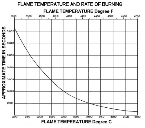
ICE automatically calculates the required CV (Clearance Volume) to suit the specified CR (Compression Ratio) in the engine data file. The Otto Cycle efficiency curve illustrates the importance of CR in relation to engine output. Both pressure and temperature affect the speed of combustion, the pressure generated at the point of ignition must be sufficient to burn the cylinder contents as the piston passes through TDC. The mixture temperature at the point of ignition determines the initial burn speed, this escalates as the combination of compression and combustion raise this further. The higher the temperature the greater the energy release within a given time scale (see Specific Heat curve). The implication of this is that the highest practical CR for the fuel mixture should be applied. This is confirmed by tests carried out by Sir Harry Ricardo with a variable compression ratio engine at modest RPM. One should appreciate these tests were carried out many years ago, the compression ratios being much lower than now applied with current Petrol grades. Detonation was a major problem at the time.
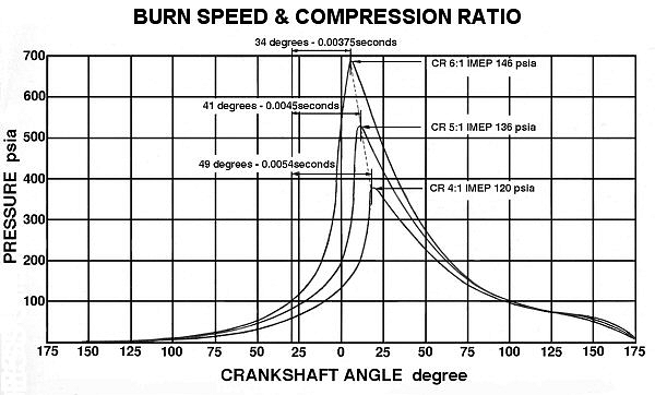
Plotting pressure versus crank rotation angle is most appropriate to illustrate the difference at alternative compression ratios, whilst the IMEP generated is indicated these are actual calculated test results. To calculate the IMEP from the pressure curve this must be plotted against Volume on the X-axis, as this must reflect cylinder displacement. The displacement per degree is not a linear function because of the crankshaft mechanism.
The mass of fuel mixture for combustion is determined by the scavenge efficiency of the engine. A 100% burn efficiency for Petrol provides approximately 48 ft.lb. per cubic inch potential energy at NTP. This value is multiplied by the Scavenge Efficiency to determine the total heat release per cycle. The program calculates the scavenge efficiency based upon mixture flow mass, trapped volume and short circuit efficiency. Users can observe the change in scavenge efficiency calculated by running the Performance function. Because the potential energy is volume based, calculation is simplified
This automatic Ignition option appears to be the most satisfactory method for engine analysis by computer, it ensures that all comparisons are made to the same base.
ICE models the combustion process based upon specific heat release data. The rate of heat release is calculated based upon a predetermined release pattern. It should be appreciated that the equations used are quadratic, the flame front progress occurs on all boundaries. The combustion period will change according to cylinder size, hence the speed of combustion calculation is related to piston speed. Burn speed varies with compression ratio, fuel and other factors. Options are provided to alter the release pattern, advance and burn speed.
The following curve indicates the variation in burn speed and compression ratio.
Whilst the program permits the User to set the burn speed this is not linked to these curves. The option to vary the burn speed permits the User to investigate how this may affect an engine's potential performance. Specific burn speeds for the fuels have not yet been implemented, whilst Test Setup has built in defaults the User should set this to suit the engine and fuel under evaluation
SETTING THE HEAT RELEASE
The program applies Triangular Heat Release, options ( A, B and C ) indicated below may be set. This diagram is not a precise indication of the pressure generated by the Heat Release Patterns. The User should observe the actual results by viewing the PV (Pressure Volume) diagram, the IMEP can be established from the Performance Tables. A rounded peak to the diagram is most unlikely because of the shape of the base compression curve, the higher the speed of combustion the closer the shape to that of the Otto Cycle (see The Otto Cycle).
The release pattern is built up from two triangles, 1st Triangle + 2nd Triangle = 1.
For example 1st Triangle = 0.5 plus 2nd Triangle = 0.5 sets
the pattern ( B ).
If the 1st Triangle is set to 1 ( 0.99 ) and the 2nd to zero ( 0.01 ), pattern
( C ) is generated.
If the 1st Triangle is set to zero ( 0.01 ) and the 2nd to 1 ( 0.99 ), pattern
( A ) is generated.
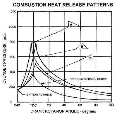
The period of combustion in degrees increases as RPM escalates, hence the Heat Release diagram above is only used to illustrate possible differences due to the release pattern. To compare cases the ignition or burn is shown starting from TDC. The diagram implies that maximum cylinder pressure may occur with the ignition timing as indicated, this is not correct. To ensure satisfactory combustion as RPM is increased Ignition Advance must be featured. The program features an automatic advance to enable the evaluation of low RPM conditions.
Whilst the program features automatic calculation of combustion period relative to cylinder capacity this is only an approximation. The equation used is related to piston speed, hence this is proportional to engine RPM, correction for bore to stroke is not applied. The user may edit the burn speed factor ratio to suit the test conditions. Both applied Ignition Advance and Combustion Period in degrees are displayed at the top of the Engine Function Tables window, the values displayed are at the maximum RPM indicated. This value is set in Combustion Speed in Test Options.