For the most effective use of Test Setup resize the window to display all of its controls.
When the program starts up User options will be loaded, if the User has not saved any options then the program defaults will be used. A message at the bottom of the Test Setup window will display which option is in use..
Command buttons at the bottom of the Window permit the user to - Save a User file or, Switch between User and Default settings. Printing the current test settings is available from the File menu - see Interface.
The Save User Settings button saves the current settings to the User file; these will be loaded as defaults the next time the ICE program is run.
Closing the Test Setup window will loose any temporary values (typed in but not saved), running any of the ICE processes is likely to recreate the window (see the second paragraph of this topic).
Tool Tips will be displayed when the Mouse pointer is hovered over items on the Test Setup form to provide HELP.
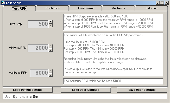
Test RPM
The Test RPM tab is used to set the minimum, maximum, and step increments for RPM. These values will be used by the initial calculation process (see Interface - the yellow and red buttons)
The RPM tab displays instructions for its use.
All of the RPM fields are numeric, and should be adjusted by clicking in the up or down arrows of the spin control. Changing the value of one field may adjust the value of others.
The RPM values should be set to suit the engine type, capacity and RPM potential. Intermediate RPM setting to examine results for that setting may be applied directly from within the Engine Function Tables or Engine Performance Tables window (see Interface - the yellow and red buttons).
The values on this tab will be used in modelling heat release, this calculates results for each degree of the 360 degree cycle.
For an explanation of how to determine the content of the items displayed on the Combustion tab see Combustion Theory.
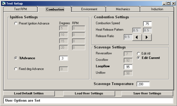
Ignition Settings - Selecting one of the options will activate the appropriate entry boxes; those that do not apply will be greyed.
![]() is set to apply an Advance Table, determined by the User. The application is similar to the Mechanical systems
fitted to many full size engines. This provides for a Fixed Advance or a
Progressive change up to a Maximum at 5000 RPM. The table of settings is discussed below.
is set to apply an Advance Table, determined by the User. The application is similar to the Mechanical systems
fitted to many full size engines. This provides for a Fixed Advance or a
Progressive change up to a Maximum at 5000 RPM. The table of settings is discussed below.
The table of values discussed in Combustion Theory is the eight boxes next to the Preset selection. The left column (Degree) should contain the degrees of advance which will be applied when the RPM entered in the second column is reached. Values should increase from top to bottom
![]() (the default) is set to apply Automatic Advance in proportion
to Burn Speed and Combustion Period. The percentage Advance is set by the
User, values from 0.01 to 1.2 (10% to 120%) can be applied. The program
applies this method by default because it ensures a satisfactory condition
irrespective of Engine Capacity and Fuel. Optimum Performance occurs close
to 50% Advance with Triangular Combustion. The advance setting is discussed below.
(the default) is set to apply Automatic Advance in proportion
to Burn Speed and Combustion Period. The percentage Advance is set by the
User, values from 0.01 to 1.2 (10% to 120%) can be applied. The program
applies this method by default because it ensures a satisfactory condition
irrespective of Engine Capacity and Fuel. Optimum Performance occurs close
to 50% Advance with Triangular Combustion. The advance setting is discussed below.
![]() is set to apply a fixed Advance angle - the default
being 10 degrees. This may be edited by the user to establish the optimum
at particular RPM increments. In other words it is complementary in establishing
a satisfactory Advance curve as would be applied by Option 1, or 2.
is set to apply a fixed Advance angle - the default
being 10 degrees. This may be edited by the user to establish the optimum
at particular RPM increments. In other words it is complementary in establishing
a satisfactory Advance curve as would be applied by Option 1, or 2.
Note- Setting 'Combustion Settings' values to zero or 1 results in these being automatically reset to 0.01 and 0.99 respectively. This is required to avoid errors in the quadratic release calculations.
Combustion Settings are used to modify the Combustion Heat Release Patterns.
Combustion Speed is a factor (.1 is 10%. 1 is 100%, 2 is 200%, etc).
Release Ratio - the spin button - is used to modify the Triangular Heat Release ratios, clicking the left arrow will reduce the left side of the slope, whilst proportionally increasing the right, clicking the right arrow will do the reverse; adjustments are in increments of .1 (10%).
Scavenge Efficiency - at the bottom right of the tab - (see Scavenge Theory) is a set of factors that are used to modify the Scavenge equations. Values must be greater than zero and less than or equal to 100. The values that appear by default are typical of the indicated scavenge systems. Modifications to these values should be based on increased or decreased efficiency of a specific engine.
Scavenge Temperature is set to 200 by default - this is a base value that is used as a start point for setting up the crankcase pump. This value should only be changed based on such criteria as poor engine cooling, unusual environments, etc.
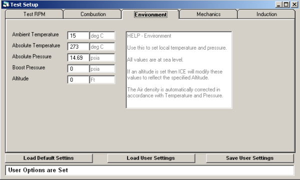
The Environment tab is used to modify the Environment in which the engine runs. Under most circumstances the values do not need modifying.
If you need to see how your engine will perform at high altitude, on the top of Everest, or at the South Pole, then this is where to set the field values.
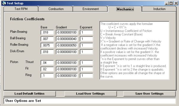
The values on the Mechanics tab are used to model mechanical efficiency.
The default values are based on average published values. Any modifications should be based of either manufactures data, or other proven sources.
For more information see Mechanical Efficiency.
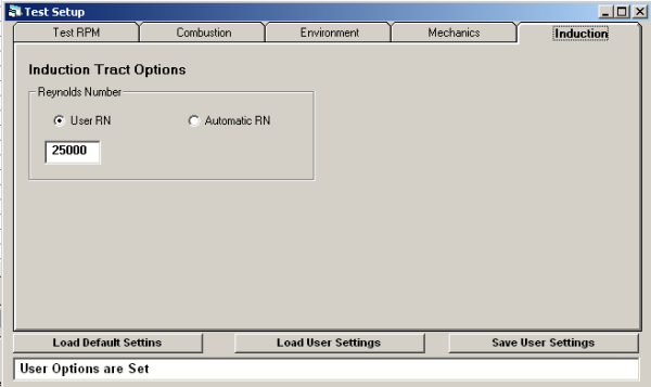
The values from the Induction tab are used to model gas flow, primarily Pulse Theory.
The Automatic RN selection will use a default Reynolds number. The User RN selection will use the value entered.
See Induction Theory for more information on the Reynolds Number.