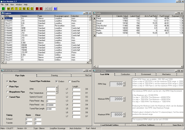
The program uses a series of MDI (Multiple Document Interface) Windows, each related to a specific function, all contained within a parent frame. The authors are not aware of any conflicts between ICE and any other software.
Certain ICE MDI Windows must be open for the program to run and should not be closed during program operation. These are - Engines, Fuels, Exhaust & Test Setup.
See the Tutorial topic Navigating the MDI Windows for ways of navigating and restoring the ICE windows.
The following list itemises all of the window types that ICE may display.
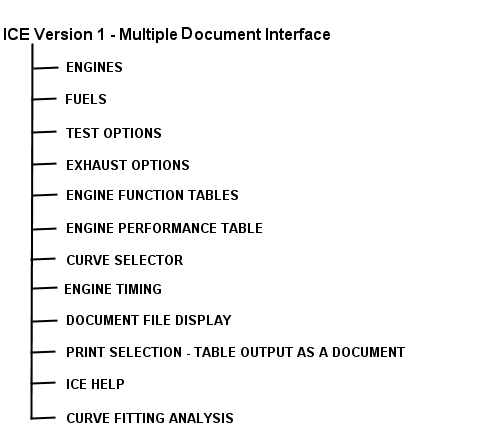
ICE Version 1.7 Menu
A common menu of functions applies to all Windows, these are -
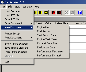
File will be the most frequently used menu, the sub-menus are used to View , Print , Save and Load Files and Graphs. The files can be read into other programs such as a Word Processor and spreadsheets to be reformatted as desired by the user. See the Tutorial topics Load,Save, and Print a document, View Document
ICE implements an extended Toolbar. The Buttons are identified by letters and colour coding. Each button uses ToolTips to displays its function when the mouse pointer is held over it (hover), hence Help is always on hand.
Within the View menu facility is provided to turn on/off the Toolbar and Ice Status bars this may be necessary to fully view Graphs and Timing diagrams.
The Window menu provides the ability move between MDI windows and display hidden windows. See the Tutorial topic Navigating MDI Windows for a fuller explanation.
![]() The
Green D button Tiles the child MDI windows.
The
Green D button Tiles the child MDI windows.
All of the Yellow buttons activate the primary calculation routines for a single, specified, RPM - case presenting the result as a numeric table with 360 rows, each containing data for that degree of rotation. The primary routine does not calculate such items as IHP, BHP etc. Each button displays a set of data specific to the button pressed (e.g. Mechanics, Flow, Thermodynamics, etc.).
![]()
The control strip above is the top of the Mechanics table. All tables are presented in a similar format, the Tutorial topic Mechanics may be used as an example for all of the Yellow buttons.
For a description of which elements of the Application Structure are addressed by the buttons listed below; please see the Application topic.
![]() The
Yellow M button (Page 1) is used to view the engine's fundamental MECHANICS.
The
Yellow M button (Page 1) is used to view the engine's fundamental MECHANICS.
![]() The
Yellow F button (Page 2) is used to view the engine's primary
GAS FLOW RATES.
The
Yellow F button (Page 2) is used to view the engine's primary
GAS FLOW RATES.
![]() The
Yellow T button (Page 3) is used to view the engine's THERMODYNAMICS
principally those associated with the Combustion Process.
The
Yellow T button (Page 3) is used to view the engine's THERMODYNAMICS
principally those associated with the Combustion Process.
![]() The
Yellow I button (Page 4) is used to view the engine's CRANKSHAFT MECHANICS the loads as generated by the crankshaft mechanism.
The
Yellow I button (Page 4) is used to view the engine's CRANKSHAFT MECHANICS the loads as generated by the crankshaft mechanism.
![]() The
Yellow S button (Page 5) is used to view the SLEEVE
VALVE MECHANICS of an engine.
The
Yellow S button (Page 5) is used to view the SLEEVE
VALVE MECHANICS of an engine.
Engines using alternative Mechanically operated valve systems will be allocated additional Page displays as the need arises. For Example an Engine using poppet valves would require additional data and routines to determine the loads and the possible affect on Mechanical Efficiency.
![]() The
Yellow E button (Page 6) is used to view
EXHAUST FUNCTION related data for a specific RPM case, through
a cycle of 360 degrees. The Pipe evaluated is set within the
EXHAUST EDITOR Window.
The
Yellow E button (Page 6) is used to view
EXHAUST FUNCTION related data for a specific RPM case, through
a cycle of 360 degrees. The Pipe evaluated is set within the
EXHAUST EDITOR Window.
![]() The
Yellow C button (Page 7) is used to view the engine's INDUCTION FUNCTION for a specific RPM case, through a cycle
of 360 degrees. For a range of RPM apply the Red E button.
The
Yellow C button (Page 7) is used to view the engine's INDUCTION FUNCTION for a specific RPM case, through a cycle
of 360 degrees. For a range of RPM apply the Red E button.
The red buttons are used to view Performance details.
![]() The
Red P button (Page 8) is used to view the engine's PERFORMANCE
details over a range of RPM.
The
Red P button (Page 8) is used to view the engine's PERFORMANCE
details over a range of RPM.
![]() The
Red E button (Page 9) is used to review the engine's ENGINE EXHAUST related to changes in
Performance due to the fitting of an Exhaust Pipe system. The Exhaust Pipe
data and design under evaluation is set by that selected in the EXHAUST
OPTIONS Window.
The
Red E button (Page 9) is used to review the engine's ENGINE EXHAUST related to changes in
Performance due to the fitting of an Exhaust Pipe system. The Exhaust Pipe
data and design under evaluation is set by that selected in the EXHAUST
OPTIONS Window.
![]() The
Blue O button is used to display the Curve Selector screen. See the Graph tutorial.
The
Blue O button is used to display the Curve Selector screen. See the Graph tutorial.
![]() The
Blue V button is used to view the last produced graph.
The
Blue V button is used to view the last produced graph.
![]() The
Blue T button is used to display the engine's Timing in the form
of a Clock Diagram. Printing the Timing diagram is via the File menu.
The
Blue T button is used to display the engine's Timing in the form
of a Clock Diagram. Printing the Timing diagram is via the File menu.